
A gear shaft is often the part that decides whether an industrial gearbox feels stable under load or begins to suffer from noise, heat, runout, and early wear. The right design balances torque transfer, shaft stiffness, tooth accuracy, surface finish, heat treatment, and inspection before the gearbox ever reaches service. For equipment builders, that means a gear shaft should be treated as a working transmission element, not as a simple shaft with teeth added to it.
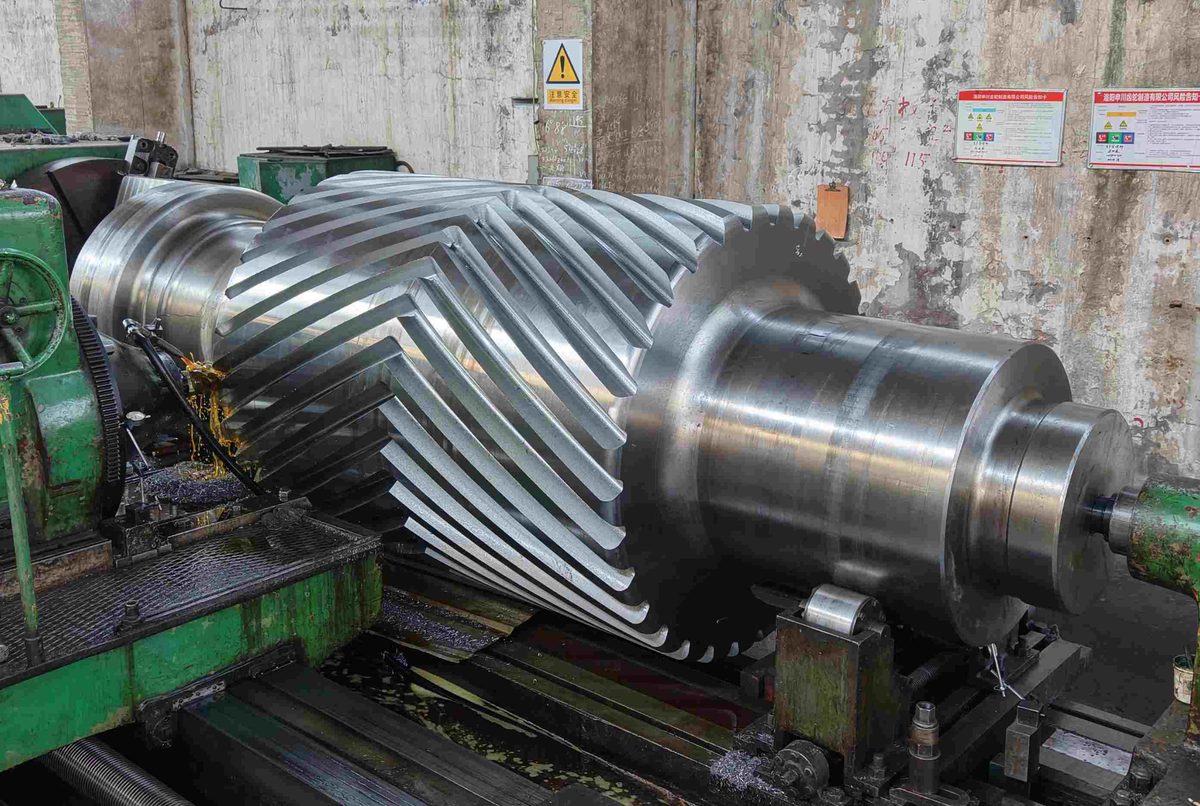
Gear Shaft Design Starts with the Load Path
A gear shaft carries torque through a single integrated component, so the tooth form, journal surfaces, shoulders, splines, and bearing seats all influence one another. When the gear and shaft are machined as one piece, there is no separate gear-to-shaft assembly clearance to manage. That can support compact layouts and accurate power transmission when the surrounding gearbox is designed around the same alignment requirements.
The first design question is where the torque enters and leaves the component. A gear input shaft may be judged by how cleanly it accepts motor torque, while a gearbox output shaft must carry the final load into the driven equipment. A pinion shaft may see concentrated tooth loading, higher speed, and stricter demands on balance and tooth contact.
YIZHI MACHINERY works best in gear shaft projects where the part is connected to a full transmission problem. The useful discussion is not only the outside diameter or the tooth count. It includes duty cycle, bearing positions, gear mesh behavior, material choice, heat treatment, and the inspection features that prove the shaft can run as intended.
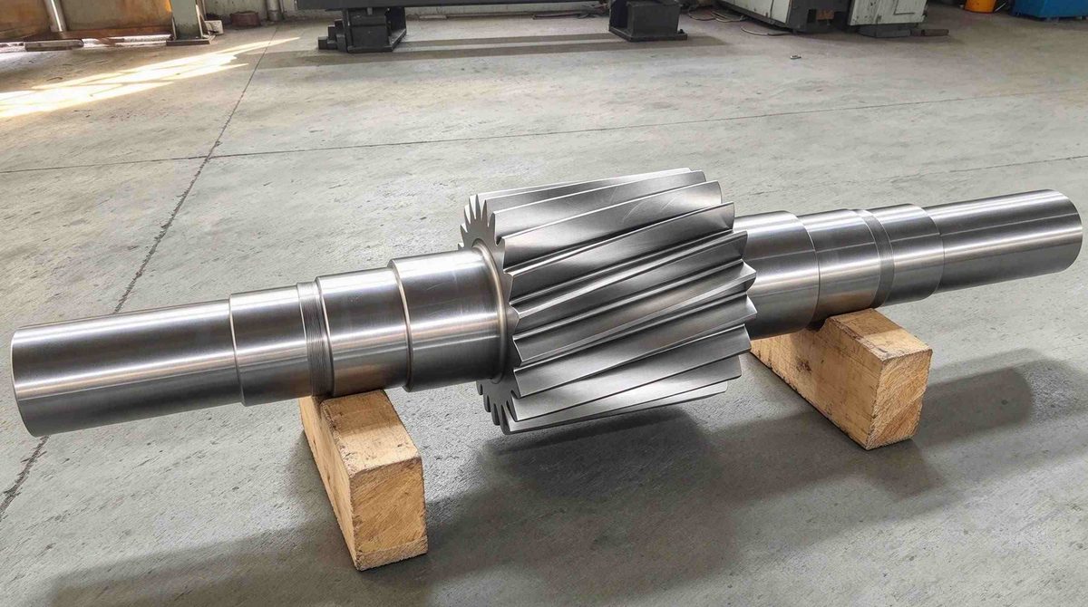
Gear Shaft Accuracy Controls Alignment and Contact
A gear shaft can look strong and still fail to run smoothly if its critical surfaces are not controlled together. Runout, concentricity, tooth profile, pitch, and surface finish all shape the contact pattern after assembly. Small errors are not isolated because the shaft journals and the gear teeth share the same load path.
Runout and Concentricity
Runout matters because the gear teeth must rotate around the same working axis as the bearing seats. If the shaft body, tooth section, and journals do not stay concentric, the mesh can tighten and relax once per revolution. The result may appear as vibration, a changing sound, local heat, or uneven wear on one side of the tooth face.
For a gear drive shaft, alignment is also affected by the gearbox housing and bearing arrangement. The shaft cannot compensate for a weak housing, but accurate shaft geometry gives the assembly a better starting point. That is why dimensional inspection and runout testing belong close to the manufacturing plan, not as a last-minute formality.
Tooth Contact and Surface Finish
The tooth surface must be accurate enough for the expected load and speed. A ground or carefully finished tooth form can reduce local stress and help the lubricant film work more consistently. In higher-duty gearboxes, a rough or distorted contact area may raise noise long before a visible failure appears.
Surface finish also matters outside the tooth area. Bearing seats, shoulders, splines, and ground shaft sections need finishes that support assembly and repeatable positioning. The best gear shaft design connects all of these features instead of optimizing one surface while leaving another to become the weak point.
Gear Shaft Manufacturing Process Choices
Gear shaft manufacturing can involve hobbing, spline hobbing, shaping, spline shaping, milling, spline milling, and grinding. Each method has a place. Hobbing is efficient for many tooth forms, shaping can suit different gear sizes and custom profiles, milling can help with smaller or specialized shapes, and grinding is used when the part needs tighter dimensional control and smoother surfaces.
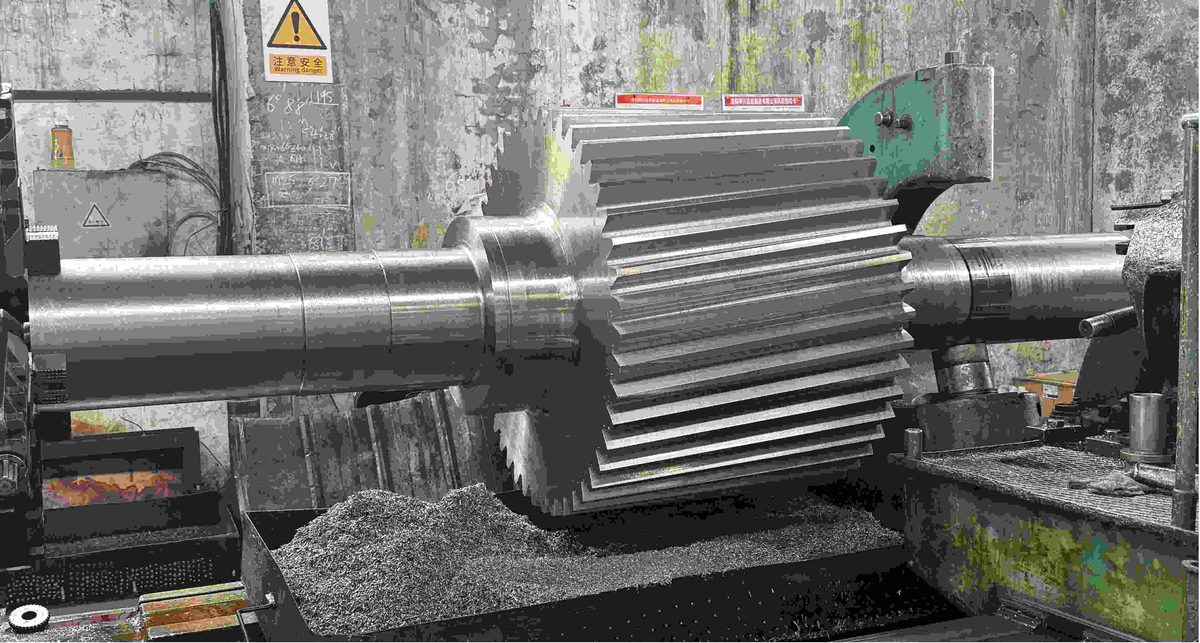
A practical process route follows the risk of the part. A shaft for moderate service may need clean machining, deburring, and conventional inspection. A gear shaft for a compact reducer, machine tool spindle, precision instrument, robot joint, or micro gearbox may need more attention to heat treatment distortion, final grinding, and the relationship between tooth geometry and journal accuracy.
Heat Treatment and Distortion Control
Heat treatment can improve hardness, strength, toughness, and wear resistance, but it also changes the manufacturing problem. Quenching, tempering, normalizing, hardening, and case hardening must be considered with the shaft geometry, tooth section, and finish requirements in mind. A design that ignores distortion risk may demand expensive correction later.
The most useful approach is to plan rough machining, heat treatment, finishing, and final inspection as a sequence. If a tooth surface needs grinding after hardening, the drawing and process route should leave room for that operation. If a bearing seat needs high positional accuracy, it should not be treated as a secondary surface.
Inspection Priorities Before Installation
A finished gear shaft should be checked through the features that control service behavior. Material inspection confirms the starting point. Dimensional inspection checks diameter, tooth thickness, pitch, shoulders, and other drawing features. Tooth profile inspection confirms that the gear section can mesh as intended.
Surface finish measurement, runout and alignment testing, load testing, and non-destructive testing can also be relevant when the application is demanding. Not every shaft needs the same inspection package, but every critical feature should have a clear reason for being checked. Documentation and traceability help keep the result connected to the drawing and application conditions.
That mindset is especially important when a gear shaft must match other custom parts. A shaft may need to fit an internal gear, bevel gear, worm gear set, coupling, bearing, or machined housing. Treating the component as part of a system reduces the chance that a correct part on paper becomes a difficult assembly in the workshop.
Where YIZHI MACHINERY Fits Gear Shaft Projects
YIZHI MACHINERY gear shaft projects can be built around product type, size, material, precision, and the surrounding transmission requirements. That is useful when the shaft is not a catalog replacement, but a part tied to the working geometry of the gearbox. The conversation can include hobbing, shaping, milling, grinding, heat treatment, and quality control from the start.
The wider YIZHI MACHINERY manufacturing capabilities also matter when a gear shaft shares a project with related components. Turning, gear grinding, ID and OD grinding, honing, gear cutting, inspection, milling, drilling, broaching, and key-seating are all relevant when the component has to connect cleanly with the rest of the transmission.
Conclusion
A gear shaft earns its value when torque, alignment, tooth contact, heat treatment, and inspection all support the same gearbox objective. The strongest design is not simply the thickest shaft or the hardest tooth surface. It is the one that keeps the load path stable, the mesh predictable, and the assembly serviceable under real operating conditions.
For a custom gear shaft path shaped around real gearbox requirements, visit YIZHI MACHINERY and connect the shaft design with the complete transmission plan.
FAQ
Q: What is the main function of a gear shaft in a gearbox
A: A gear shaft transfers torque while supporting the gear teeth, bearing surfaces, and alignment features that keep the gearbox running smoothly. Because the gear and shaft are integrated, the component can reduce assembly clearance and support compact transmission layouts when the surrounding housing and bearings are designed correctly.
Q: When should a gearbox use an integrated gear shaft instead of a separate gear and shaft
A: An integrated gear shaft is useful when compactness, rigidity, and transmission accuracy matter more than easy gear replacement. It can suit small reducers, machine tool spindles, precision instruments, robot joints, and micro gearboxes. The tradeoff is that damage may require replacement of the whole component.
Q: Which inspections are important for gear shaft reliability
A: Important inspections include material checks, dimensional measurement, tooth profile inspection, surface finish measurement, runout and alignment testing, and hardness verification when heat treatment is involved. Demanding applications may also require load testing or non-destructive testing to detect flaws before installation.
Q: How does heat treatment affect a gear shaft
A: Heat treatment can improve hardness, strength, wear resistance, and toughness, but it may also create distortion that affects tooth contact and shaft alignment. The process should be planned with rough machining, finishing, grinding, and inspection so the final gear shaft matches both the drawing and the gearbox application.
